What is used to control the attenuation of RF signals by a PIN diode?
A. Forward DC bias current
[E6B11]
B. A sub-harmonic pump signal
C. Reverse voltage larger than the RF signal
D. Capacitance of an RF coupling capacitor
This question from the new Amateur Extra question pool dives head first into the operation of a PIN diode.
What’s a PIN diode? The PIN is an abbreviation for the P-Type, Intrinsic, and N-Type layers of the device, which describes the construction of the diode.

The wide intrinsic layer means that under no current the PIN diode basically acts like a low-value capacitor, which does not pass an RF signal well.
Apply even a small bias current and the device turns into a low-value resistor instead, which will freely pass an RF signal. This turns it into an effective RF switching device.
From Wikipedia:
The PIN diode obeys the standard diode equation for low frequency signals. At higher frequencies, the diode looks like an almost perfect (very linear, even for large signals) resistor. The P-I-N diode has a relatively large stored charge adrift in a thick intrinsic region. At a low enough frequency, the stored charge can be fully swept and the diode turns off. At higher frequencies, there is not enough time to sweep the charge from the drift region, so the diode never turns off. The time required to sweep the stored charge from a diode junction is its reverse recovery time, and it is relatively long in a PIN diode. For a given semiconductor material, on state impedance, and minimum usable RF frequency, the reverse recovery time is fixed. This property can be exploited; one variety of P-I-N diode, the step recovery diode, exploits the abrupt impedance change at the end of the reverse recovery to create a narrow impulse waveform useful for frequency multiplication with high multiples.
The high-frequency resistance is inversely proportional to the DC bias current through the diode. A PIN diode, suitably biased, therefore acts as a variable resistor. This high-frequency resistance may vary over a wide range (from 0.1 Ω to 10 kΩ in some cases;[1] the useful range is smaller, though).
The answer is A. Forward DC bias current

photos:
https://en.wikipedia.org/wiki/File:Pin-Diode.svg
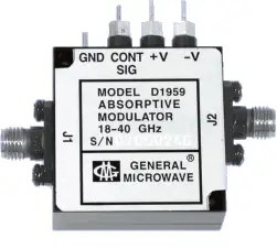
https://en.wikipedia.org/wiki/File:General_Microwave_Modulator.png
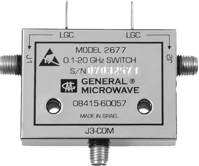
https://en.wikipedia.org/wiki/File:Microwave_Switch.png

